IP Routing is all about sending information from one IP address to another. That might sound like a straight forward thing to do, but it gets a bit complicated, because a destination IP address often belongs to a completely different network than the source IP address. How do we find the correct device? To properly identify a device we not only need the IP address, we need to find out the destination device MAC address too. But there is a catch: MAC addresses can only be queried on a local network (using a protocol called ARP). So the challenge here is: We want to send info across multiple networks, but we are only able to identify devices using a mechanism that works within the borders of a local network!
IP Routing happens on layer 3 and 2 of the OSI Model: In layer 3 (Network layer) you create an IP Packet with IP Address information. In layer 2 (Data Link layer) you create an Ethernet frame with MAC Address information.
Routing within the same network
IP routing is best explained by example. So in this example we send a ping from 10.0.0.10 to 10.0.0.20, so everything within the same network. No router required. The device 10.0.0.10 starts with creating an IP Packet on layer 3 (yes, “packet” not “package”). We have all the required information available for the IP packet:

- Source IP: 10.0.0.10
- Destination IP: 10.0.0.20
- TTL 128
- Other = Data
- ICMP is the protocol used for pin
TTL (Time To Live) starts with 128 and is decremented by 1 each time the packet traverses a router. If it reaches 0, then the packet is thrown away. That is to prevent endless routing of an IP packet.
After the IP Packet was created a layer 2 frame is created. The packet will be the data of the frame:

- Source MAC Address: 000C29FC70A5
- Layer 3 Protocol: IPv4
- Data: IP Packet (displayed red)
- Destination MAC Address of device with IP 10.0.0.20: We don’t know yet
To resolve the Destination MAC address we use ARP (Address Resolution Protocol) protocol. ARP creates its own layer 2 frame:

- Destination MAC Address: FFFFFFFFFFFF (all F’s is broadcast, ask everyone in the current network)
- Source MAC Address: 000C29FC70A5
- Layer 2 Protocol:: ARP
- Data: “Who has MAC Address belonging to 10.0.0.20?”

Eventually device 10.0.0.20 will answer the request by adding its MAC address and sending the frame back to 10.0.0.10. Now 10.0.0.10 has all the info to send the ping. 10.0.0.20 receives the ping request and uses the containing info to reply back to 10.0.0.10.
Generally speaking: ARP allows us to get a layer 2 information (the MAC address) using info from layer 3 only (the IP address). ARP maintains an ARP Cache on each device in the network, which is simply a table storing MAC Addresses and their corresponding IP for 90 seconds only. ARP table is not the MAC Address table that we know from Switches, because the Switch table does not deal with IP addresses.
On Windows you can type arp -a to see the ARP cache for each network interface. You will also see IP addresses there like 224.0.0.x! Those are MultiCast addresses (see Class D in Classful Addresses above). And there are also broadcast addresses like x.x.x.255.
Routing between different networks
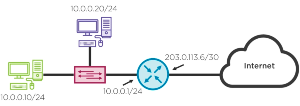
A router is defined as a device that has at least two network interfaces, each interface has an IP of a different network assigned. A gateway is just another name for router, they mean the same thing. The internet is full of router devices.
A router is always used when data from network is sent to another network. Here is an example: Let’s say you want to send a ping request from 10.0.0.10 to 192.168.10.8. Both IP addresses are clearly on different networks. What you need to properly send the request is the MAC Address of the device that is behind 192.168.10.8. If the machine was on the same network, then you would simply send an ARP broadcast and one of your devices would respond with the queried MAC Address. But sending an ARP request on the 10.0.0.x network asking “Who has MAC Address for 192.168.10.8?” does not make sense, because ARP only deals with local network IPs. So instead, we want to get the MAC Address of our router, so we ARP for our router on 10.0.0.1. How do we know that the router has IP address 10.0.0.1? Our device was configured that way!
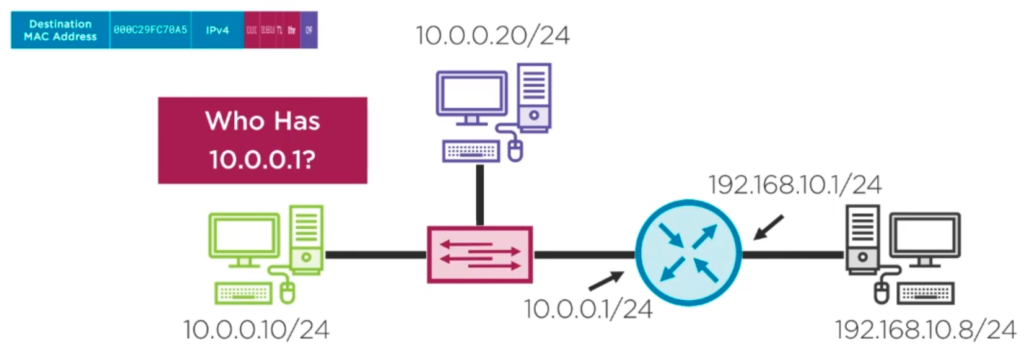
We receive the MAC Address of the router, set it in the layer 2 frame and sent the request to the router. The router looks at the IP Packet: “This packet is intended for Destination IP address 192.168.10.8. Do I know how to reach that? Let me have a look in my routing table if I have a network using 192.168.10.0/24. Yes, I have such a network connected to me!”. The router is now rebuilding the frame: The Source MAC Address becomes the one of 192.168.10.0/24. The Destination MAC Address is acquired via ARP. The PC with 192.168.10.8 answers. The router fills in the MAC Address as destination and sends the info to the device.
Multiple routers
As already mentioned each router has at least two network interfaces which connect two different networks together. The Network Address of each connected interface is stored in the routers IP Routing table. If a IP Packet arrives the router and the destination IP address does not belong to any of the connected networks, then the router simply throws away the Packet. So the goal is to add routes to each of the routers, so that each router knows how to reach all the networks in the system.
In the following example we are dealing with 3 routers and 4 networks.
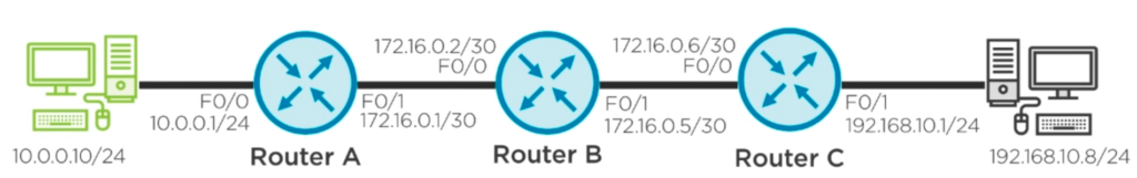
Router A is connected to 10.0.0.0/24 and 172.16.0.0/30.
Router B is connected to 172.16.0.0/30 and 172.16.0.4/30.
Router C is connected to 172.16.0.4/30 and 192.168.10.0/24.
Let’s send a message from 10.0.0.10 to 192.168.10.8 over 3 routers (or hops): 10.0.0.10 sends IP Packet to Router A. Router A sees that destination IP is 192.168.10.8. It looks up its routing table and sees an entry of a matching Network Address of 192.168.10.0/24 -> B, so the router forwards the message to Router B. Router B looks up its routing table and sees an entry for 192.168.10.0/24 -> C and forwards the message to Router C. Router C is directly connected to 192.168.10.8 and sends the message to the device. On every router traversal the IP Packet’s TTL is reduced by 1.
How do routers find the correct routes? One option is to configure them statically in your router. With Dynamic Routing a routing protocol determines the best path to each destination network. Additionally if there is a failure to a redundant link, dynamic routing will recalculate the best path. This is similar to using GPS in a car. There are several routing protocols, such as the outdated RIP (Routing Information Protocol), EIGRP (Enhanced Interior Gateway Routing Protocol), OSPF (Open shortest path first) and BGP (Border Gateway Protocol) which is the primary protocol used on the internet. It allows Internet Service Providers to create business contracts with each other and then implement a routing plan based on the business established contract.
Trace route (Tracert)
Tracert is a tool to follow the routing paths from source to destination, showing all involved routers and how long the requests take. Run tracert -d 8.8.8.8 to trace the route to a Google Server.
About Author

I am Mathias from Heidelberg, Germany. I am a passionate IT freelancer with 15+ years experience in programming, especially in developing web based applications for companies that range from small startups to the big players out there. I create Bosycom and initiated several software projects.